Efficient Solutions for Industrial Needs
Planar sheet measuring machine
Fast and accurate 2D/3D measurement system for flat parts, suitable for quality monitoring and reverse engineering. Award-winning technology offers an easy user experience and comprehensive reporting capabilities.
InspecVision Planar – Optical Inspection Measurement Top Technology
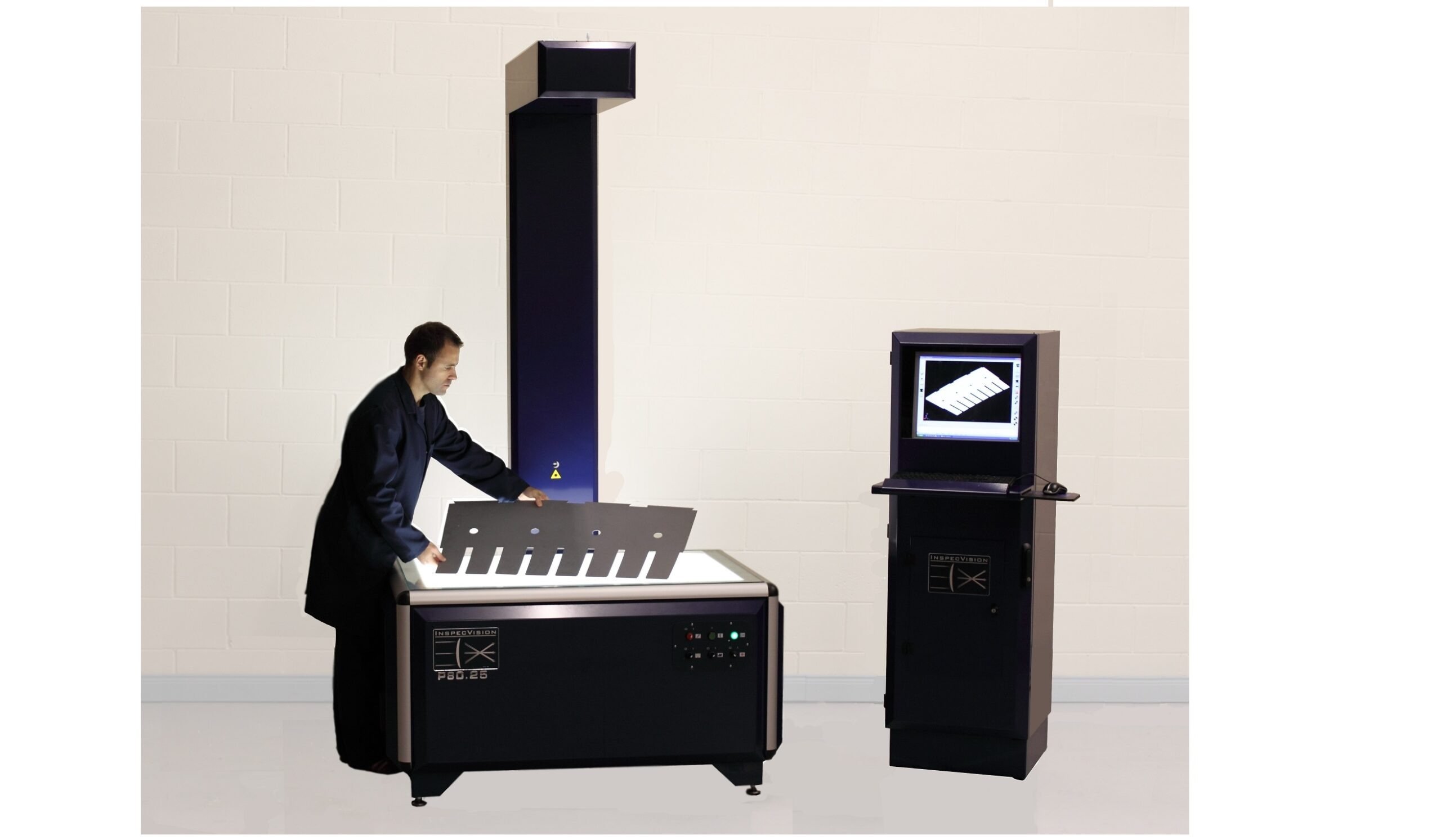
InspecVision Planar represents the world’s fastest and most versatile two-dimensional inspection system, developed to meet the strict quality requirements of modern manufacturing. The system is specifically designed for precise measurement of thin sheet metal parts, seals, and other flat components. The technology is based on a fixed measurement table and a ultradetailed digital camera, which allows for the analysis of even complex parts in seconds instead of traditional, slow measurement methods.
The device’s operating principle is exceptionally efficient, as it does not contain any moving mechanical parts. This structure ensures excellent operational reliability and minimizes maintenance needs, while eliminating the risk of measurement inaccuracies caused by wear. The user places the part to be measured on the light table, and the system automatically compares it to the stored image of the original CAD model. The software immediately produces comprehensive reports and visualizes any deviations, enabling real-time optimization of the production process and minimizing waste.
The Planar product family offers a wide range of models of different sizes and with various degrees of accuracy, which can cover very diverse production needs from small-batch production to mass production. The system’s scalability is one of its most significant advantages, and it can be equipped with additional modules that allow for, for example, the measurement of surface profiles and advanced reverse engineering. The reverse engineering feature allows a precise digital file to be created from a physical part in seconds, which significantly speeds up product development and spare parts manufacturing.
InspecVision Planar is designed to be integrated directly into the production environment. Its durable structure and tolerance to temperature variations make it a reliable tool for factory conditions. The system not only improves the level of quality control, but it also acts as a strategic investment that increases the productivity and competitiveness of the entire manufacturing chain by reducing the need for manual labor and eliminating human measurement errors.
| Model | Accuracy | Maximum Part Size (mm) | Maximum Allowable Weight (kg) | |||
| Form | SurfScan | Length | Depth | Height | ||
| P17.12 | 12/25µm | 0.1mm | 500 | 333 | 120 | 100 |
| P43.100 | 100/200µm | 0.3mm | 810 | 520 | 250 | 25 |
| P70.20 | 20/40µm | 0.15mm | 1000 | 667 | 350 | 50 |
| P110.25 | 25/50µm | 0.15mm | 1276 | 851 | 350 | 200 |
| P150.35 | 35/70µm | 0.2mm | 1500 | 1000 | 350 | 250 |
| P220.35 | 35/70µm | 0.25mm | 1830 | 1220 | 350 | 400 |
| P220.50 | 50/100µm | 0.25mm | 1830 | 1220 | 350 | 400 |
| P360.35L | 35/70µm | 0.25mm | 3000 | 1220 | 350 | 500 |
| P360.50L | 50/100µm | 0.25mm | 3000 | 1220 | 350 | 500 |
| P370.50 | 50/100µm | 0.3mm | 2355 | 1570 | 350 | 500 |
| P370.100 | 100/200µm | 0.3mm | 2355 | 1570 | 350 | 500 |
Lataukset
Planar 2D brochure
Opti-Scan 3D
The Planar system’s modularity enables flexible customisation of the equipment and upgrades even later, thanks to pre-installed factory wiring. The key Opti-Scan 3D add-on module turns a 2D measuring device into a full-blooded 3D system using white-light scanning.
This globally unique solution measures both surfaces and edges in seconds. The system automatically compares the generated point cloud to the CAD model and visualises deviations with a clear colour map. Powerful software produces instant measurement reports and supports the most common CAD formats, ensuring an accurate and fast quality assurance process.

Surfscan (2.5D)
Surfscan is a perfect choice when measurements such as height are needed. The point cloud obtained from the scan can also be compared to a CAD model.

Dimensioning
One special feature of the Planar system is its unique ability to perform reverse engineering of flat parts very quickly. A profile can be placed in the machine and an image and model are obtained in seconds. The machine saves dxf or dwg CAD files that can be fed into cutting systems to make copies, or simply to document the part if no documents exist. Familiar CAD functions allow the user to edit and clean data, standardise hole sizes and perform edge cleanup before saving the file. Physical parts, plain white paper, acetate, gaskets or even electronic images can be saved as CAD files. When using the 3D option, the same can be done for 3D parts.
